
1.9 Print and Export the Map
With your map elements arranged on your layout, you are finally ready to create your first project output: a printed map. In many cases, though, it may be more useful to export your map as a PDF document or image file. Exporting the map to a PDF document allows you to easily transfer it to a different computer, view it, and print it outside of ArcGIS Pro.
The layout you designed in the last two sections is intended for printing, and can also be used to generate a PDF document. However, it is not really suitable if you intend to just use the map in digital form, say on a website or in a slideshow presentation. For those uses, the layout and map elements should be resized to fit screen specifications, and exported as an image file.
When sizing a digital layout, you should think not in inches or centimeters, but in pixels, the units in which screen dimensions are measured. You should also think about the aspect ratio, or the ratio of width to height of the image. These dimensions vary by device and change frequently, but there are some conventions you can go by. In the early 2000’s, most computer monitors were CRT screens with a 4:3 aspect ratio, and the most common screen size was 1,024 pixels x 768 pixels. These are still appropriate dimensions for an image that will be embedded into a web page. Today, most computer and TV screens use a 16:9 aspect ratio. The default size of a Microsoft PowerPoint presentation slide is 1,280 pixels x 720 pixels, so you may want to use this size if you will show your map using a projector. Another common 16:9 screen size is 1920 pixels x 1080 pixels; this is good for higher-resolution displays.
The image resolution defines how finely detailed the image is. Because screens can inherently show less detail than paper, map images meant for screens are output at a lower resolution than maps meant to be printed. The generally accepted standard is to use 300 dots per inch (dpi) for an image that will be printed and 72 ppi (pixels per inch) for a screens-only image (dpi and ppi are treated interchangeably in ArcGIS Pro). For more information about how dpi/ppi is applied in each setting, see the “Dots per inch” Wikipedia article.
Section Outcomes
In this section, you will:
- print the layout,
- export the layout as a PDF document,
- copy the map for a second layout,
- create a new layout for screen viewing, and
- export the screen layout as an image.
 Print the layout
Since you already designed your printable layout in Sections 1.7 and 1.8, printing it is very easy. The only trick is knowing where to find the print button in the ArcGIS Pro interface.
1. With the Layout View active, click the Share ribbon tab.
2. In the Output group of the Share ribbon tab, click the “Print Layout” button, which has an image of a printer.
3. In the Print Layout pane, choose a printer that is on and connected to your computer from the “Printer Name” dropdown (Figure 1.43).
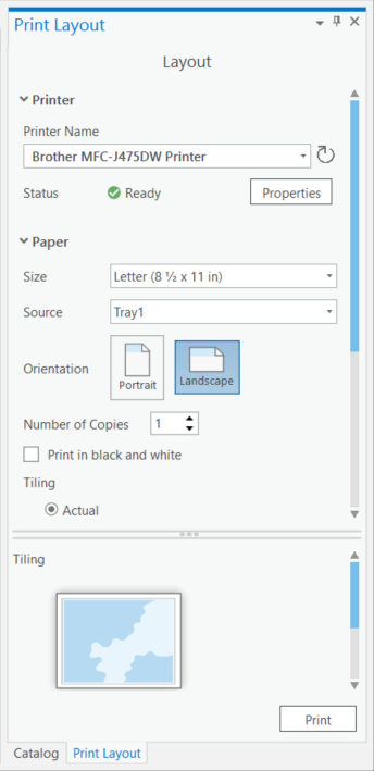
4. Under “Paper”, ensure the paper Size and Orientation match your layout page size and orientation, that the “Print in black and white” checkbox is unchecked, and that “Tiling” is set to “Actual”.
5. Examine the “Tiling” preview at the bottom of the pane to ensure it looks like the layout will fit the page correctly. If it does not, readjust the paper settings to ensure they match the layout dimensions.
6. Click the “Print” button.
7. Examine your printed map to ensure it printed correctly.
![]() Teachback 31 – Evaluation
Teachback 31 – Evaluation
How does your printed map look compared to the Layout View in ArcGIS Pro? Did anything surprise you about how it turned out when printed?
Export the layout as a PDF document
There are many situations for which you may need a document in a standard format that can be printed outside of ArcGIS Pro. Perhaps you need to print from a different computer than you used to make your map, and ArcGIS Pro is not installed on it. Perhaps you want to share your map with someone else who does not have ArcGIS Pro in a way that allows them to print it themselves. For these purposes, the best output is a PDF version of your map. Exporting as a PDF is also simple and requires no changes to the layout.
8. In the Output group of the Share ribbon tab, to the right of the Print button, click the “Export Layout” button.
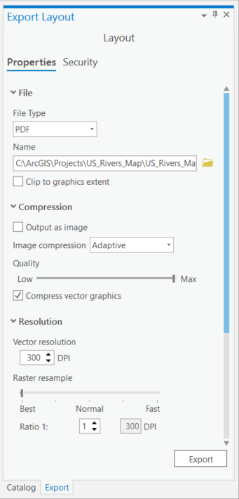
9. In the Export Layout pane, under “File”, change the “File Type” dropdown to “PDF” (Figure 1.44).
10. Under “Name”, to the right of the input, click the Browse button (the yellow folder icon).
11. In the Export window, navigate to your project folder, enter a file name for your document ending in a .pdf extension, and click the “Save” button.
12. In the Export Layout pane, ensure the “Clip to graphics extent” checkbox is unchecked.
13. Under “Compression”, move the “Quality” slider to “Max”.
14. Under “Resolution”, set “Vector resolution” to 300 DPI (if it isn’t already).
15. Leave all other options in the pane as the defaults and click the “Export” button.
16. In Windows Explorer, navigate to your project folder and open the .pdf file to ensure it exported correctly.
![]() Teachback 32 – Evaluation
Teachback 32 – Evaluation
Try printing the PDF document. Does its printout look the same as the printout generated directly by ArcGIS Pro? If not, how do they differ?
Copy the map for a second layout
Here is where things start to get tricky. Certain parameters of your map, such as its scale, the sizes of points and lines, and the sizes and placement of labels, are perfected for a particular layout size and view setting. In this case, you created a map that was intended for printing. However, if you want your map to look its best on a different layout designed for viewing on screens, you may need to adjust some things. It’s a good idea to start by duplicating your map before creating a second layout, so that you can change the look of map symbols and labels to fit screens while preserving the original map for printing.
17. In the Catalog pane, expand the “Maps” item at the top of the list.
18. Under “Maps”, right-click on the map, then click “Copy”.
19. Right-click on “Maps”, then click “Paste”.
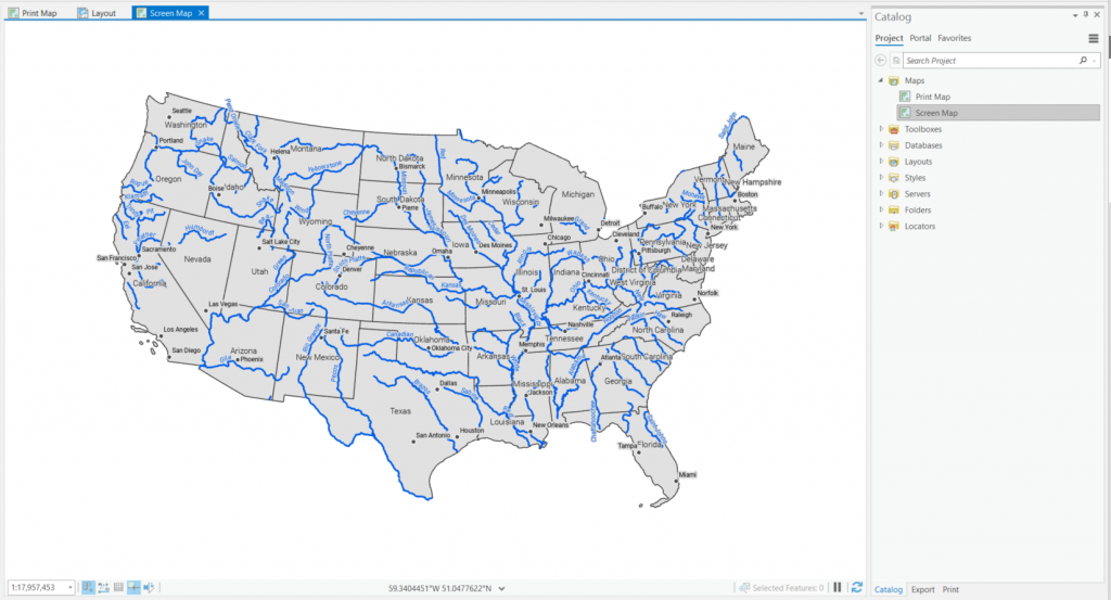
20. Under “Maps”, rename “Map” to “Print Map” and rename “Map1” to “Screen Map”.
21. Right-click on “Screen Map”, then click “Open”.
Create a new layout for screen viewing
You have learned how to create a layout, and how to export it; now you will practice these skills to make a map document that is designed to be viewed on a screen. Given the lower resolution of screens than printing, you will need to think carefully about how you size your layout, and resize the map elements for a smaller page. ArcGIS Pro uses points as units for sizing layouts based on screen dimensions. Points are primarily used for sizing type, and there are 72 points to an inch; thus, when you export the layout at a resolution of 72 ppi, 1 point equals 1 pixel. Instead of recreating all of your map elements from scratch, you can copy and paste your print layout elements onto your screen layout, then resize them as necessary. One important step to remember, though, is to change the map frame’s contents from the print map to the screen map, to ensure that you do not mess up your print map elements as you are designing your screen layout.
22. In the Project group of the Insert ribbon tab, click the “New Layout” button.
23. At the bottom of the New Layout dropdown, click “Custom page size…”.
24. In the Page Setup tab of the Layout Properties window, change “Page units” to “Point” (Figure 1.46).
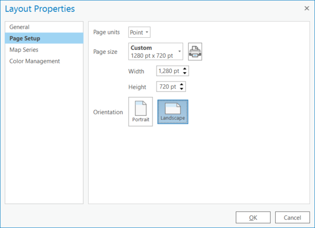
25. Under “Page size”, change “Width” to 1280 pt and Height to 720 pt, the standard dimensions of a presentation slide (or use other screen dimensions of your choosing).
26. Click the “OK” button.
27. Save the project.
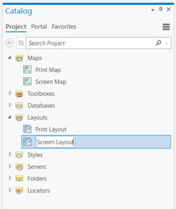
28. In the Catalog pane, expand the “Layouts” item, then rename “Layout” to “Print Layout” and “Layout1” to “Screen Layout” (Figure 1.47).
29. At the top of the Center View, switch to the “Print Layout” tab.
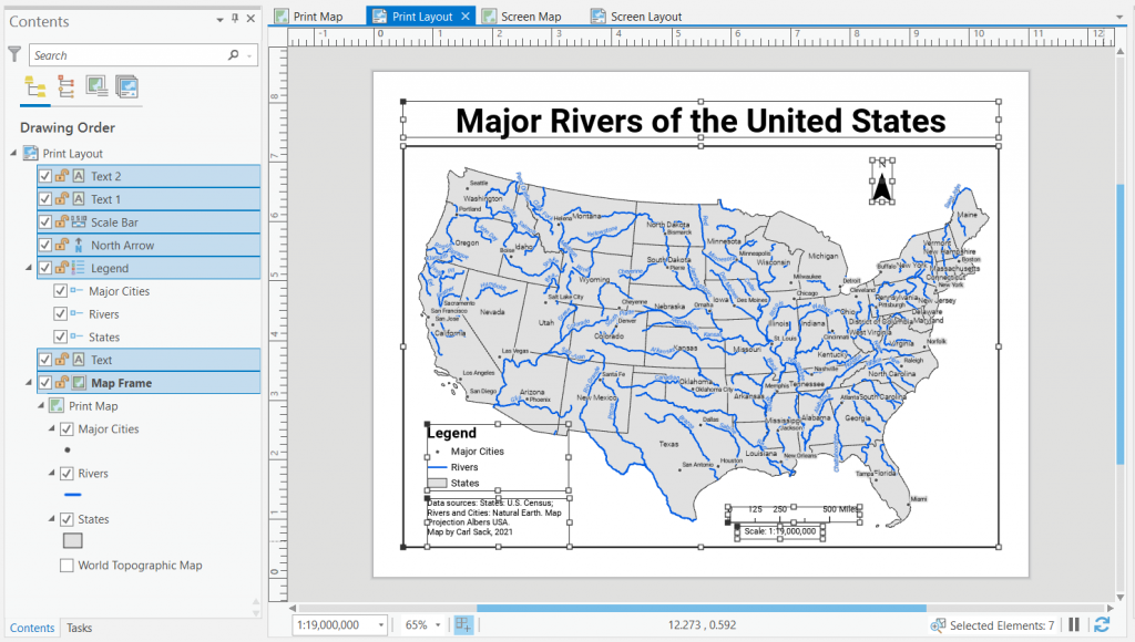
30. In the Contents Pane, under “Print Layout”, click the top item to select it, then hold the Shift key on your keyboard and click the bottom item (probably the map frame; Figure 1.48). Alternatively, hit Control-A on your keyboard.
31. Right-click on one of the selected map elements, then click “Copy”. Alternatively, hit Control-C on your keyboard.
32. In the Center View, switch back to the “Screen Layout” tab.
33. Right-click on the layout page, then click “Paste”. Alternatively, hit Control-V on your keyboard.
34. Save the project.
35. In the Contents pane, right-click on the “Map Frame” item, then click “Properties”.
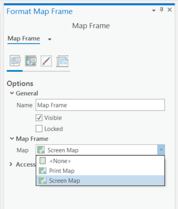
36. In the Format Map Frame pane, in the Options tab (the left-most button, which looks like a layout with a speech bubble), under “Map Frame”, change the “Map” dropdown to “Screen Map” (Figure 1.49).
37. Resize the map frame to fit the page. If using a fluid layout with no frame border, make its width the full page width (1,280 pt); if using a compartmentalized layout with a frame border, leave even margins on each side. See Section 1.7, Steps 7-10 to review how to size the map frame.
38. Activate the map. See Section 1.8, Steps 14-17 to review how to activate, scale, and close activation of the map.
39. Rescale and center the map to fit the map frame.
40. Increase the sizes of labels for each layer. Use a minimum 10-point font size (suitable for screen viewing). See Section 1.5, Steps 7-8 to review how to adjust the appearance of labels.
41. Close the map activation.
42. Select each of the other map elements in turn and adjust their position and appearance for the new layout. Ensure all text uses at least 10-point font size. As you are editing, you may make mistakes; keep the Undo button in the title bar in mind! See each element’s action sequence in Section 1.8 to review how to adjust the element.
43. When you are finished making adjustments to the layout, save the project.
![]() Teachback 33 – Perception, Interpretation, and Evaluation
Teachback 33 – Perception, Interpretation, and Evaluation
Briefly describe the changes you needed to make to set your map up for export as an image for screen viewing.
Export the screen layout as an image
Documents that are intended to be viewed on screens commonly use a resolution of 72 ppi. For maps, the best screen-viewing image format is PNG. This format is considered a web standard, meaning web browsers can display PNG images that are embedded in websites. The other web standard image formats you may be familiar with are GIF and JPEG. GIF is an older format that supports animation. JPEG is best for continuous images such as photos, as it stores pixels in a way that smooths hard edges. In contrast, PNG is good for maps that use vector linework, as it tends to preserve the fidelity of edges and lines.
44. In the Export group of the Share ribbon tab, click the “Export Layout” button.
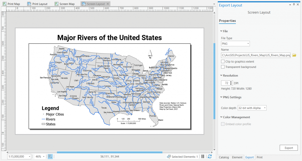
45. In the Export Layout pane, change the “File Type” dropdown to “PNG” (Figure 1.50).
46. Under “Name”, to the right of the input, click the Browse (folder) icon.
47. Navigate to your project folder, name the file, and click the “Save” button.
48. Ensure that the “Clip to graphics extent” checkbox is unchecked. You may wish to check the “Transparent background” checkbox if you want the background of your map to be hollow; to keep it white, leave this unchecked.
49. Under “Resolution”, change the input to 72 DPI.
50. Click the “Export” button.
51. From your project folder in Windows Explorer, open the .png file to ensure it exported correctly.
![]() Teachback 34 – Evaluation
Teachback 34 – Evaluation
- View both your PDF map document and your PNG map image side-by-side on your computer screen, or switch back and forth between the two. What is different between the two versions of your map?
- What changes could you make to each version of the map to improve it?
What if I want to add the map to a larger printed document?
The map layout you designed in Sections 1.7 and 1.8 is intended for standalone printing, and its dimensions may not make it suitable for embedding in a larger printed document (such as a report or poster). The new layout you created for screen viewing would be either too small or too low resolution if printed this way. To save time, this section does not directly cover the process of resizing and exporting the layout for embedding in a larger printed document, but here are some pointers.
First off, create a new layout that is sized using inches or centimeters according to the usable area of the document in which it will be placed—not including any margins or column gutters. For instance, in the U.S., most word processing documents use 1-inch margins, so if the full page size is 8½” x 11” and the page is portrait-oriented with one column, the column width is 6½” (if landscape-oriented, it would be 9”). This should be the maximum width of your new layout.
Once you size your layout, copy your map elements over from your original print layout, and resize them on the page. You may want to tweak the font sizes of labels and map elements to fill the space on the page without too much crowding, but keep them sized appropriately for printing (i.e., no smaller than 6-point font). One element you can probably discard entirely is the title, since in a larger document it is best to use a caption to fulfill the same purpose.
When you are ready to export your new layout, set the export resolution to 300 dpi and save the exported document as a PNG or TIFF image. Both formats are good for vector graphics such as maps. If you save as a TIFF, use LZW image compression; this will result in a smaller file size with no loss of quality. When you place the map in your larger document, do not resize it. Since you already set the layout size based on the document’s usable area, it should come in at the correct size.
Further Resources
Additional information about printing from ArcGIS Pro is available on the ArcGIS Pro Help website “Print a map or layout” page. Additional information about exporting a layout to various file formats is available in the “Export a map or layout” pages.
Portable Document Format; an international standard file format for viewing, sharing, and printing documents
Picture element; a single cell of a raster image containing one attribute or color value
The ratio of the width of an image to its height
The level of detail in an image, often measured in pixels per inch
Units used for measuring the font size of type; 1 point equals 1/72 of an inch
Portable Network Graphics, a web standard image file format best for displaying vector graphics in raster form
Graphics Interchange Format, a bitmap image file format that supports animation and can be embedded in web documents
An image file format that is widely used for photos, including on the web, and supports varying levels of lossy compression
Tagged Image File Format, an image format that supports multiple color models and lossless LZW compression
