
1.8 Add Map Elements
A map is more than a collection of symbols and labels. To make your map effective, you need to include other map elements that give its users context to interpret what’s on the map. These may include a title, legend, scale indicator (e.g., a scale bar or representative fraction), direction indicator (e.g., a north arrow or compass rose), author, publication date, metadata (information about the map’s data sources and projection), and ancillary information about the subject matter of the map.
Not all of these elements must be included in every map, but most maps use at least some of them to present the map in an aesthetically pleasing way and aid understanding. Elements should be arranged to produce visual balance, so things on the page look even, with no large blank spots or crowded areas. Creating a map layout is both an art and a science—it should lead to an aesthetically pleasing map set up to guide the user’s thinking toward the information and ideas you want them to take away from it. For more on map layout and elements, see Section 9.3 in the Campbell and Shin text.
Section Outcomes
In this section, you will:
- add a title,
- adjust the title,
- add a legend,
- rename feature layers,
- reorder legend items,
- adjust legend display options,
- adjust legend text,
- add a direction indicator,
- add a scale bar,
- add scale text, and
- add metadata and authorship information.
 Add a title
Almost all maps have a title. The exceptions are usually maps that are embedded in a larger web page or document, which generally use a caption instead. In most cases, though, a title is needed to quickly inform users as to the subject matter of your map. It should be both concise and descriptive, including the “what” and the “where” of your map. It is also a good idea to match the typeface of the title to that of your labels (or at least use a typeface which does not clash with the labels). ArcGIS Pro gives you several options for inserting title text, but all of them will allow you to adjust the appearance of the text to your liking after you create it.
1. Click the Insert ribbon tab.
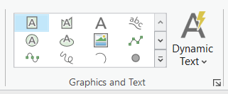
2. In the Graphics and Text group of the Insert ribbon tab, click the “Rectangle” button (which has an icon of a green rectangle with an “A” in it; Figure 1.34).
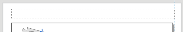
3. Move your mouse until the cursor aligns with the left edge of your map frame and a vertical dashed blue line appears.
4. Hold down your left mouse button and drag to the right across the layout page until your cursor is even with the right edge of the map frame and the dashed box snaps to the dashed blue line, then let go of the mouse button to place the text frame (Figure 1.35).
5. Type the name of the map, then click anywhere outside of the text frame.
6. Save the project.
Adjust the title
If you need to change the text that is inside the text frame, you can do so at any time by double-clicking on it. Like the Format Map Frame pane, the Element pane populates when the text is selected. Once the text is deselected, you can select it again by clicking on it once while the Select tool is active in the Layout ribbon tab, or by clicking on its item in the Contents pane. If the Element tab is not open, you can open it by right-clicking on the Text item in the Contents pane, then clicking “Properties”.
7. In the Element pane, under the “Text” tab, click the Options icon (the left-most icon, which looks like a page with a callout).
8. Expand the General, Text, and Paragraph options. Experiment with each option to see what it does to the title.
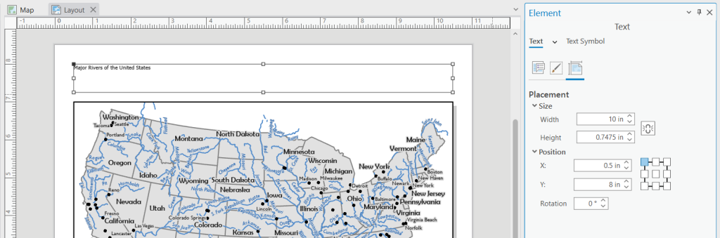
9. Click the Placement icon (the right-most icon, which looks like a page with measurement bars on the top and left side).
10. Under Position, click the upper-left box in the nine-box square graphic to set the text frame origin to the upper-left corner.
11. Adjust the X, Y, and Width values so the title’s text frame has the same margin around its left, top, and right sides as you used for the three uniform sides of the map frame (Figure 1.36).
12. If your title is inside your map frame, you may wish to return to the Options area and set a Margin greater than zero to allow some space between the frame and the title text.
13. Click on the Display icon (the middle icon, which looks like a dotted box with a paintbrush).
14. Make sure the “Border”, “Background”, and “Shadow” symbols are set to “No color”.
15. Above the icons, click “Text Symbol”.
16. With the “Properties” tab and “General” icon (which looks like a letter “A” with a paintbrush) selected, expand “Appearance” (Figure 1.37).
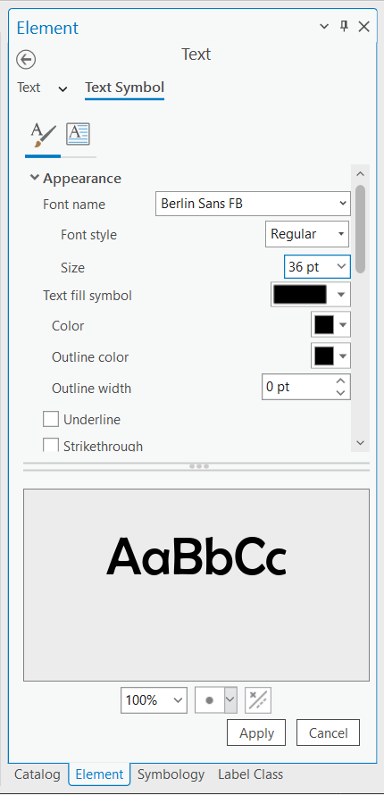
17. Adjust the text appearance options. Click the “Apply” button at the bottom of the Element pane each time you make an adjustment.
18. Deselect the text frame (click anywhere outside of it on the Layout View) so you can see how the title looks without a frame around it, then re-select the text frame by clicking on the title once or by clicking on its item in the Contents pane.
19. Continue adjusting the text appearance options to your liking, applying each adjustment and deselecting the text frame to observe the title as it will appear on the printed page.
20. With the text frame selected, scroll down to the properties below Appearance and expand each one to observe what other options you have for adjusting the title text. Make any adjustments you think improve the look of the title.
21. When you are satisfied with the title, save the project.
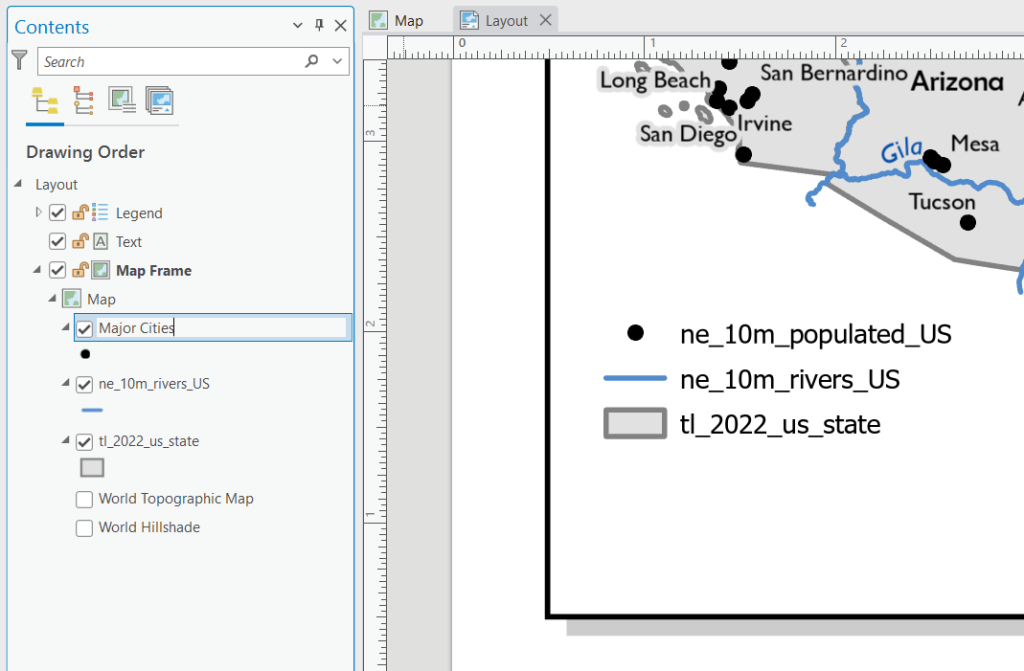
Add a legend
A legend defines the meanings of symbols that may not be obvious to the map’s users. Most maps should have a legend of some kind, though it may not need to include every map symbol if the meanings of some symbols are obvious. The placement of your legend should visually balance other elements on the layout; look for the largest or squarest blank spot you can find on the page and stick it there for starters (you can always move it). ArcGIS Pro creates legends dynamically, so changes to map layers automatically update the way they appear in the legend. Nonetheless, like labeling, getting the look of the legend just right can take a lot of fiddling and requires patience.
22. In the Navigate group of the Layout ribbon tab, click the “Navigate” button.
23. Zoom the layout to the area of the page where you would like to put your legend.
24. In the Map Surrounds group of the Insert ribbon tab, click the “Legend” button.
25. Draw your legend on the page.
26. Save the project.
Rename feature layers
27. In the Contents pane, under “Map Frame” and “Map”, click once on the name of the point layer, then click on it again to make it editable. Alternatively, right-click the layer name, then click “Properties”, and edit the “Name” field in the General tab of the Layer Properties window.
28. Type a new name for the layer, then hit the Enter key on your keyboard (Figure 1.38).
29. Repeat the above process to rename each of the feature layers.
30. Save the project.
Reorder legend items
31. In the Contents pane, under “Layout”, expand the “Legend” group.
32. Under “Legend”, click and drag the bottom legend item to a position just above the top legend item.
33. Order the legend items the way you think looks the best.
34. Save the project.
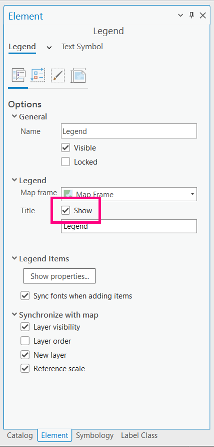
Adjust legend display options
35. In the Contents pane, click on “Legend” to populate the Element pane with Legend options. (If the Element pane is not open, right-click on “Legend” in the Contents pane, then click “Properties”).
36. In the Element pane, under the “Legend” tab, click the Options icon (the first icon on the left, which looks like a page with a callout).
37. Under “Options”, check the “Show” checkbox to the right of “Title” (Figure 1.39).
38. Under “Legend Items”, click “Show properties…”
39. Examine and experiment with the Legend Item options, observing the effect of each on the legend.
40. Above the “Legend Item” tab, click the back arrow to return to the main Legend options.
41. Under the “Legend” tab, click the Legend Arrangement Options icon (second from left, which looks like legend items with arrows along the top and side).
42. Examine and experiment with the Arrangement options, then return them to their default settings. (Because your legend is simple, you will not actually need to adjust anything here for the final legend).
43. Save the project.
Teachback 29 – Perception and Interpretation
- What happens in the Contents pane when you click the “Show properties…” button under “Legend Items” in the Format Legend pane (Step 38)?
- What is displayed in the Element pane when you select a single Legend item in the Contents pane?
- Which Arrangement options (Step 42) had an effect on something in your legend? What did they do?
Adjust legend text
44. At the top of the Element pane, to the right of the “Legend” tab, click the small dropdown arrow, then click “Title”.
45. Adjust the appearance of the legend title to your liking. Set it to the same typeface you used for the map title.
46. At the top of the pane, click the small dropdown arrow next to the “Title” tab, then click “Labels”.
47. Adjust the appearance of the legend labels to your liking. Use a typeface that you used for your titles or map labels.
48. Zoom out on the layout page and reposition the legend so it fills space on the page as evenly as possible, balancing the map symbols and other elements.
49. Save the project.
Add a direction indicator
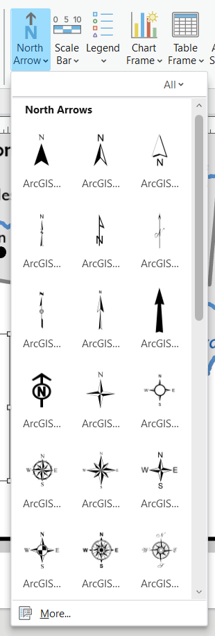
A direction indicator is useful if your map’s geography may not be familiar to users, or if the map is rotated so north is not “up”. It is not really necessary on maps of familiar geography (like the continental United States), but many include one anyway. The most common kinds of direction indicator are the north arrow and the compass rose. ArcGIS Pro gives you several of each to choose from.
50. In the Map Surrounds group of the Insert ribbon tab, click the “North Arrow” dropdown button, then choose your preferred direction indicator (Figure 1.40).
51. Draw a box to place the direction indicator in a blank space on the layout.
52. Adjust the position and size of the direction indicator to your liking.
53. Save the project.
Add a scale bar
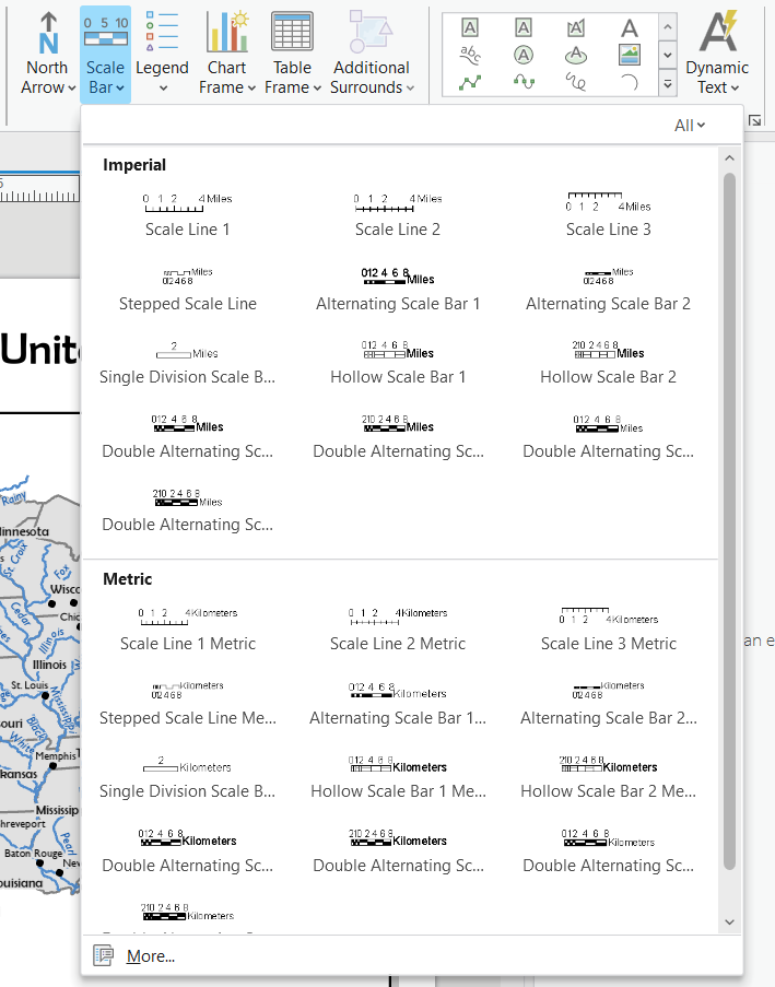
A scale indicator tells the user how big things are in the world relative to how they appear on the map. There are three types of scale indicators: a scale bar, representative fraction, and relative scale (or verbal scale). Only a scale bar maintains its accuracy if the map is viewed on a screen, because screen sizes vary and the scale bar changes size along with the map. It is best to use rounded distances for the tic marks or sections of the scale bar, as they make it easier to interpret. The other two scale types can be useful if you are designing a printed map, especially at a large scale, as they allow users to easily calculate how large certain features on the map are.
54. In the Map Surrounds group of the Insert ribbon tab, click the “Scale Bar” dropdown button, then choose your preferred scale bar design (Figure 1.41).
55. Draw a long, narrow box in a blank space on the layout to place the scale bar.
56. Click the resizing handle in the middle of the right side of the scale bar frame and drag it to the right or left to adjust the length of the scale bar. Repeat this adjustment until the distance numbers are round (e.g., multiples of 10 or 100).
57. If desired, adjust the Scale Bar options in the Element pane to your liking (for example, make sure the text uses the same typeface as your legend labels).
58. Adjust the position of the scale bar on the layout to your liking.
59. Save the project.
Add scale text
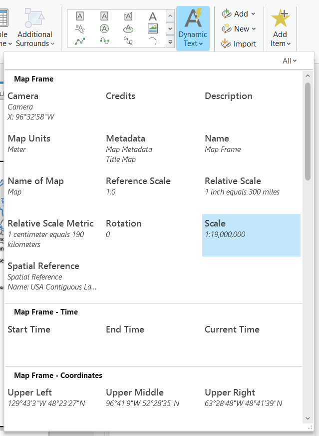
Like the scale bar, the numbers used in scale text should be rounded numbers to aid their interpretation. You should have entered a rounded number for the map frame’s representative fraction scale in the previous section, but if necessary, adjust this input now.
60. In the Text group of the Insert ribbon tab, click the “Dynamic Text” dropdown button.
61. Under “Map Frame”, click “Scale” (Figure 1.42).
62. Draw a box on the layout for the dynamic text frame (which contains a representative fraction scale).
63. If desired, adjust the options in the Element pane to your liking. Make sure the typeface matches your legend labels and scale bar.
64. Repeat the process in Steps 58-61 to place a relative scale.
65. Adjust the positions of all three scale representations on the layout to your liking.
66. Save the project.
Add metadata and authorship information
Metadata is information about your data sources, map projection, and anything else important for users to know about how you made the map. Don’t skip it! Crediting your sources is not only an ethical imperative, it provides an argument to your users that your map is authoritative. You should also credit yourself! Include your name and the date you made or most recently edited the map, so users will know how current the information on it is. All of this information is usually included in a single concise paragraph, in small font size.
67. In the Text group of the Insert ribbon tab, click the “Rectangle” button.
68. Draw the text box in the layout.
69. Type a list of your data sources, your name, and the current year.
70. In the Element pane, click the “Text Symbol” tab, and adjust the appearance and position of the text to your liking. Use a small font size and the same typeface as your legend labels and scale representations.
71. Adjust the position of the text on the layout to your liking.
72. In the Contents pane, rename each of the Text items to indicate what they are (title, representative fraction scale, relative scale, and metadata).
73. Save the project.
Teachback 30
There are many different map elements you can add to a layout in ArcGIS Pro, but all of them have a similar set of adjustment options in the Element pane. In a paragraph of your own words, describe how you open this pane for a given element, and how the options in the pane are organized.
Further Resources
Additional information about working with map elements is available on the ArcGIS Pro Help website “Work with layout elements” page and the pages that are linked within it.
Components of a map layout that improve its aesthetics and/or provide contextual information to map users
A map element that indicates the relationship between the sizes of things on the map and their sizes in the real world
Information about data or a map, possibly including its source, author(s), included attributes, dates, scale, coordinate reference system, projection, etc.
The impression of evenness of design elements on a page or graphic
A map element that defines the meanings of symbols used on the map
A map element that graphically indicates the lengths on the map of key distances in the real world
A representation of map scale as a ratio of distance on the map to distance on the ground.
A written statement of the relationship between a length on the map and its corresponding distance in the real world
See "relative scale"
